Overview
As a part of my college curriculum, I had the chance to model the mechanical stresses that spinal implants place which integrated into the body.
Due to the addition of spinal fusion to spinal features, stress can become localized in other areas of the spine or the implant rather than distributed along the area of concern. Focusing on lumbar spinal fusions, this stress shielding can lead to disc degeneration and localized spine osteopenia, and in cases where the spinal implant is explanted, spinal fractures can occur. Using finite element analysis (FEA), the biomechanical response to the spinal fusion process was able to be simulated. By generating an implant mesh in contact with the spine, areas of the implant with increased stress concentrations can be quantitatively and visually demonstrated, informing surgeons and spinal fusion device designers of future design constraints.
Methods
For the FEA models, the loads that the lumbar spine experiences are complex due to the wide area of factors present. The simulation scenario that I’ve developed is a person carrying a 20 kg load with outstretched arms and bending at a 20 degree angle. This scenario was chosen because it is the greatest action that induces increased stress in the lumbar spine. In the scenario, the factors that contributed to the loads on the lumbar spine are simplified to the tension of muscles posterior to the spine, the external forces and moments due to the state of the body; and the gravitational forces from the mass of the upper body.
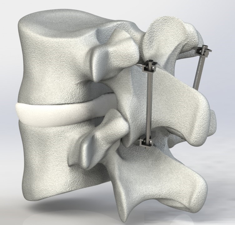
To model lumbar spinal fusion, the geometry of the problem included the L3 and L4 vertebrae with an implanted orthopedic spinal fusion implant system. Two separate FEA models will be developed, one including the spinal fusion system, and one that does not. The FEA models were built and solved using ANSYS. The vertebrae model was modeled by Robert “Jay” Jones and obtained from GrabCAD. The spinal fusion implant was modeled by Ersin and also obtained from GrabCAD. Both models were modified in SolidWorks to simplify the total geometry for the FEA solver.
Results
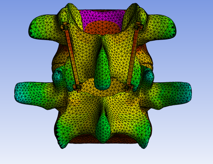
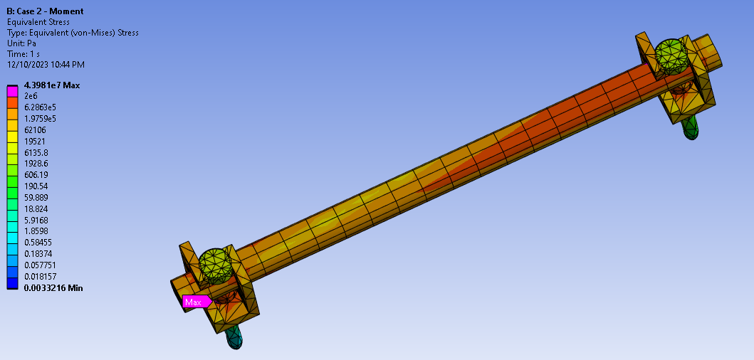
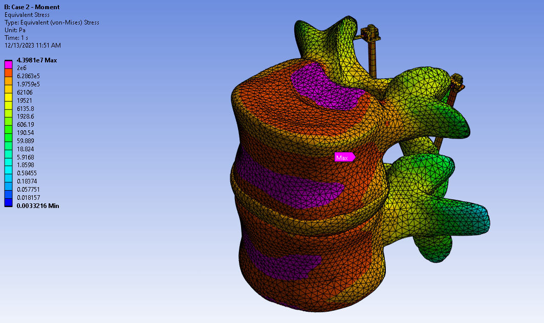
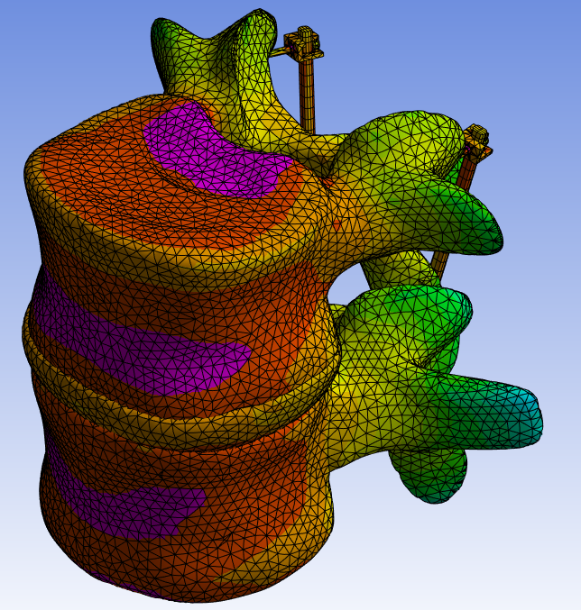
In Case 1, the maximum observed stress was 9.04 MPa, while in Case 2, it was 43.98 MPa. In the pedicle screws, the highest observed stress was around 3.7 MPa, and in the spinal rod it was around 3 MPa.
The maximum stress location shifted from the anterior-superior faces of the L4 vertebrae to the posterior-inferior face of the L3 vertebrae once the spinal implant was included in the model. Also, through visual inspection of the models, a reduced stress concentration in the anterior vertebral region can be seen. There is also a visible gradient of stress concentrations in the spinal rod, with stress concentrating in the superior area, along with the pedicle screws.